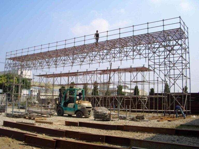



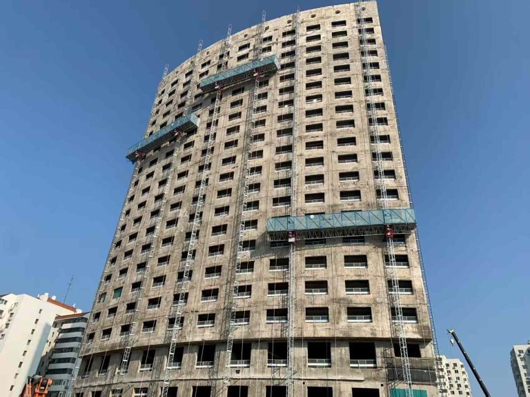

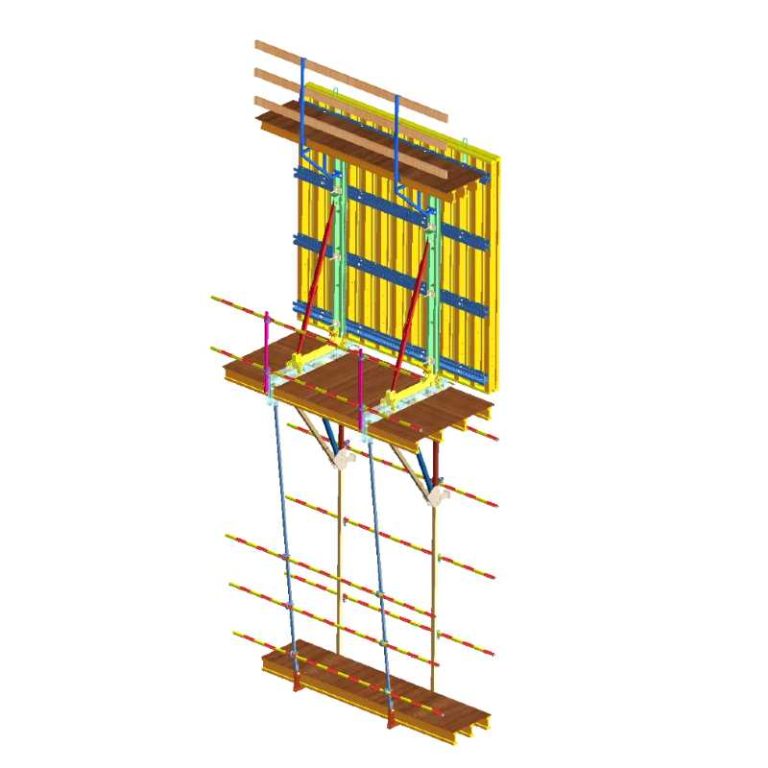
A shoring scaffold should be designed as a temporary load-bearing structure, not as posts under a formwork deck. Before concrete work begins, define loads, trace a continuous load path, verify the supporting surface, control height and bracing, and coordinate the frame with reinforcement, access, pouring, stripping, and reshoring. Check the final arrangement against project drawings, manufacturer instructions, and approval procedures.
What Loads Must a Shoring Scaffold Carry During Concrete Work?
Include Fresh Concrete, Formwork and Construction Loads
The design load is more than fresh concrete. It can include formwork, beams, shoring members, reinforcement, workers, tools, hoses, placing equipment, and local effects during placement. Establish the load cases required for the pour instead of applying a rule of thumb.
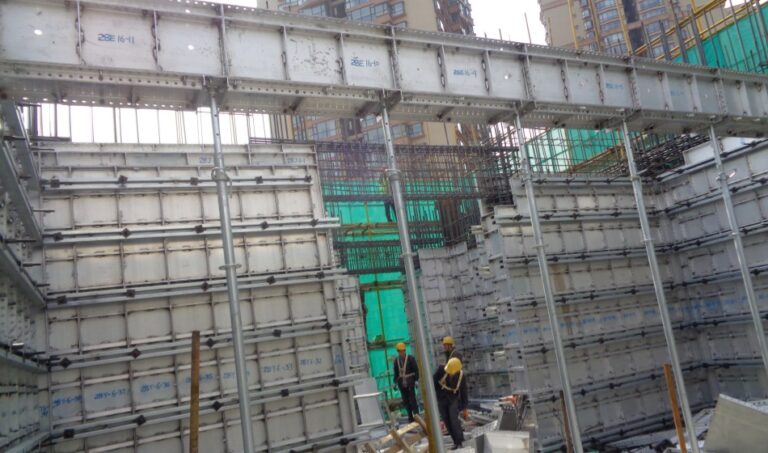
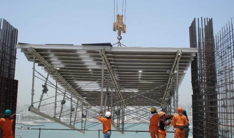
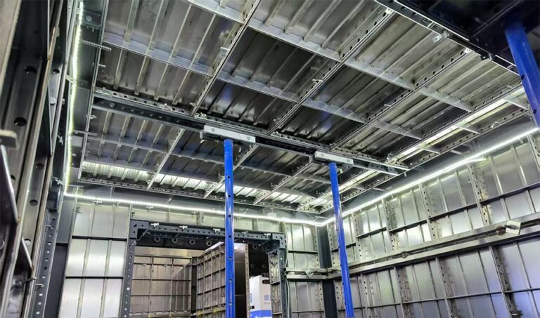
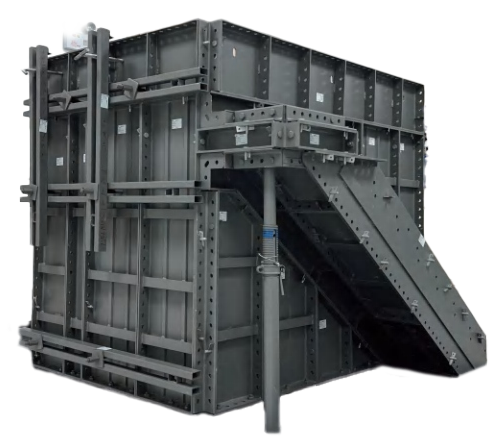
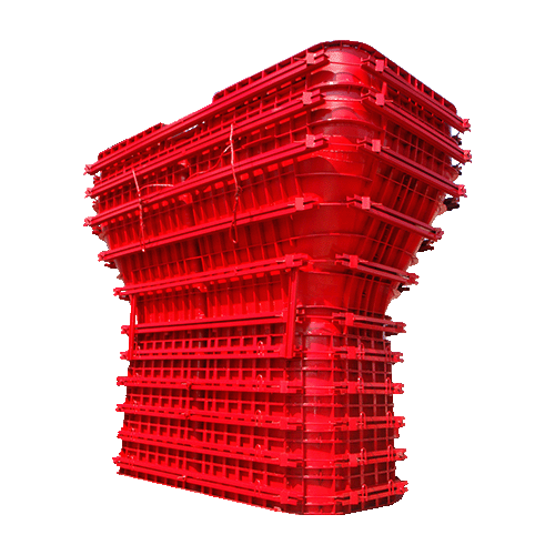
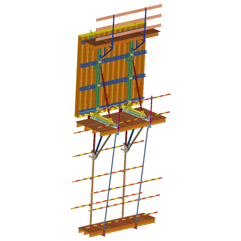
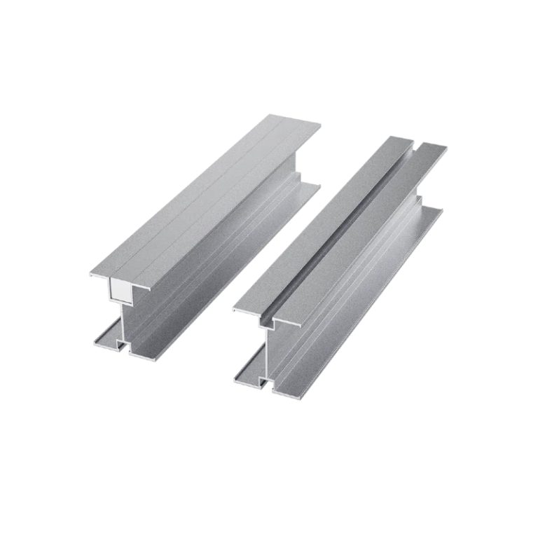
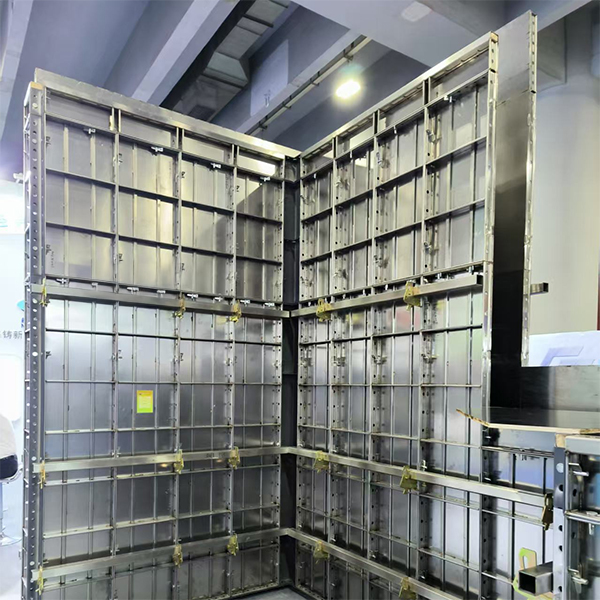
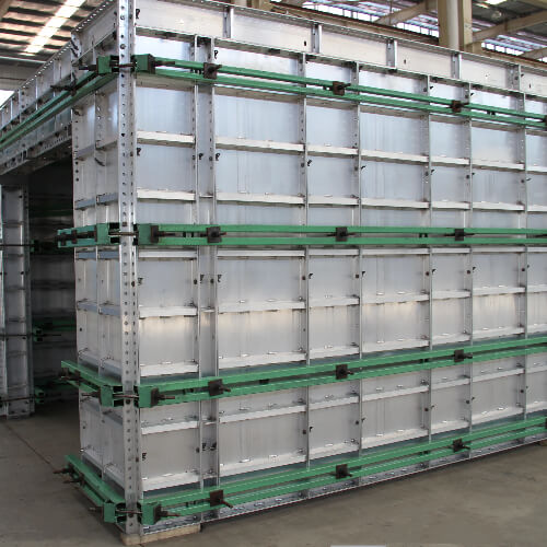
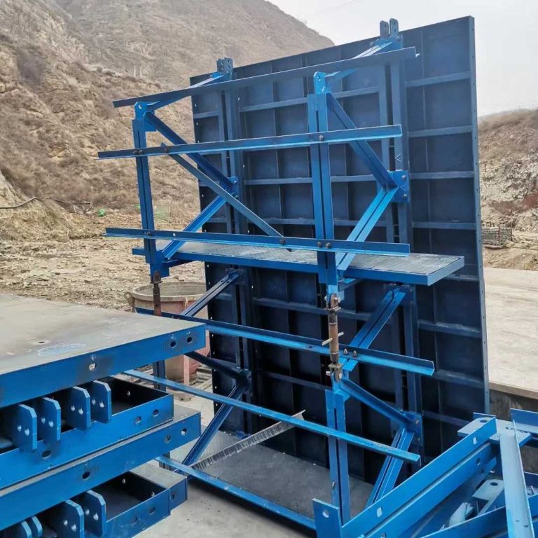
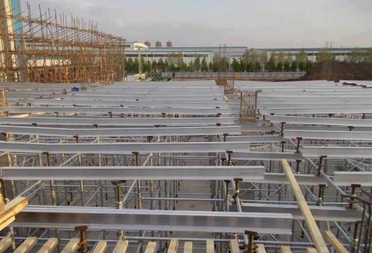
Formwork and shoring should be reviewed together. For example, an aluminium formwork arrangement may combine top formwork with prop systems, while beam and slab formwork transfer reactions through different members. An Aluminium Beam can be part of a formwork support arrangement, but its suitability still depends on the actual span, reactions, connections, and project design.
Check Beam Zones and Other Areas With Concentrated Reactions
Uniform slab loading is only one part of the review. Beams, drop panels, transfer zones, slab edges, openings, construction joints, and changes in formwork direction can create concentrated reactions. A layout that works in the open slab area may be unsuitable below a deep beam or transfer member.
Mark these zones on the formwork plan before setting out the shoring scaffold. Confirm whether additional standards, closer support points, stronger bearers, or a different arrangement are required. Check whether each reaction reaches a member and connection verified for that load.
Verify the Slab, Ground or Structure Receiving the Shoring Loads
Every support reaction must finish on an approved surface. Check slab thickness, construction age, reinforcement layout, ground bearing, backfill, voids, slopes, and the structure below. A strong shoring scaffold can still fail if the slab cracks, ground settles, or the load reaches a weak patch.
Use sole plates, spreaders, or other load-distribution measures only when included in the approved design. A larger base plate does not automatically make an unverified surface adequate. Where the scaffold stands over an earlier floor, check whether lower floors require back-propping or a planned load-transfer sequence.
How Should a Shoring Scaffold Create a Continuous Load Path?
Trace Loads From Formwork Beams Into Head Supports
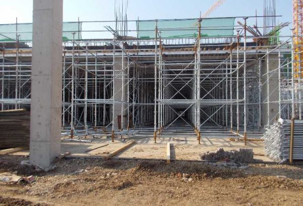
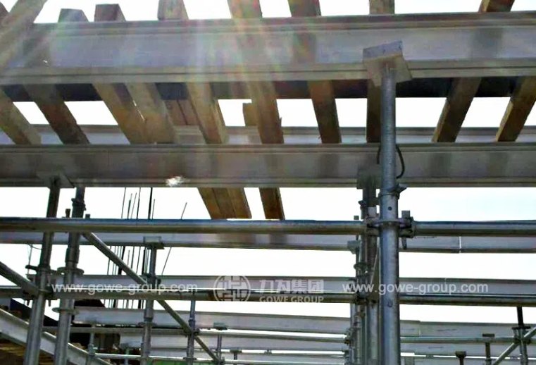
Start at the concrete and work downward. The load should pass from the form face into secondary beams, primary beams, head supports, standards, base components, and the supporting slab or ground. Each interface needs clear bearing and a connection detail that prevents sliding, eccentricity, or local crushing.
Adjust head supports so formwork beams are properly seated and aligned. Avoid unsupported gaps, unstable packing, point contact, or a head arrangement that transfers the reaction outside the standard axis. If beam lines change direction, show the transition instead of relying on site improvisation.
Transfer Reactions Through Standards and Bracing
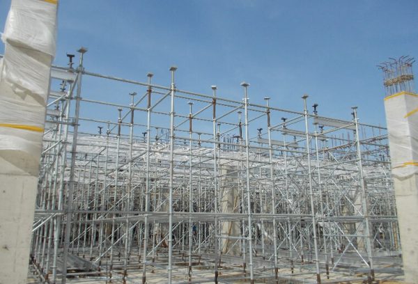
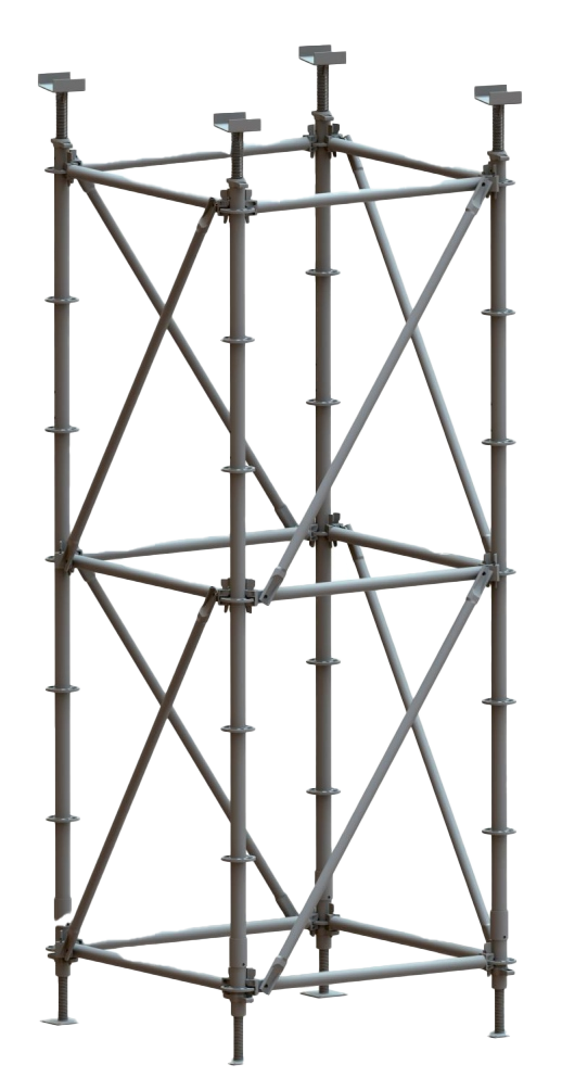
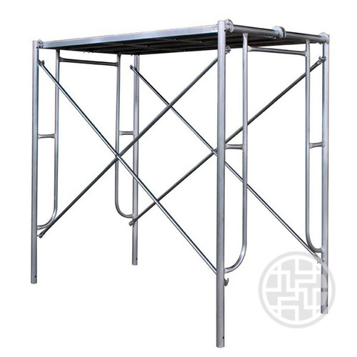
Standards carry axial reactions, while ledgers and diagonal braces help maintain geometry and control horizontal actions. In a ringlock system, standards, ledgers, diagonal braces, base jacks, base collars, and head jacks or U heads work as a connected arrangement. Wedge-pin connections are intended to secure the members and transmit load and horizontal force through the assembled system.
A ringlock frame cannot carry any shoring load by assumption. The selected system, connection condition, height, bay arrangement, bracing pattern, and load case must match manufacturer information and the project design. Inspect every connection as part of the load path.
Spread Base Reactions Into the Approved Supporting Surface
At the bottom, confirm that base jacks, collars, plates, sole boards, and spreaders are arranged as shown in the design. Keep the load centered and control differential settlement. If a base must be offset, packed, or stepped, that condition needs an engineered detail.
The load path is complete only when the surface can accept the reaction without unacceptable bearing stress, punching, sliding, settlement, or rotation. Record the approved surface and restrictions in the site handover package.
How Do Height and Layout Affect Shoring Scaffold Stability?
Coordinate Bay Spacing With the Required Support Points
Bay spacing should follow the required support points and formwork beam arrangement. Do not select a convenient grid and force the beams to fit later. Review slab panels, beam lines, column heads, openings, edge conditions, pour strips, and access corridors together.
For irregular geometry, the layout may need several bay sizes or local strengthening. Show each change on the drawing and check its effect on axial load, stability, erection sequence, and material movement.
Control Adjustable Head and Base Extensions
Adjustable components help with leveling and fitting, but excessive extension can reduce stability or change support behavior. Confirm the permitted adjustment range, thread engagement, locking method, and bearing condition from the applicable instructions.
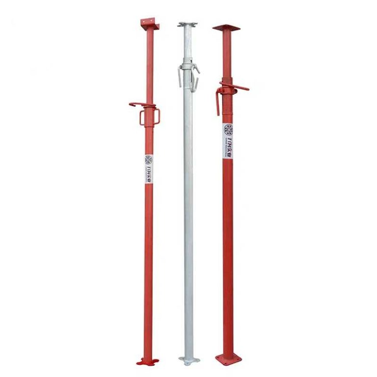
A Steel Prop may suit a particular vertical support task, but a product name alone is not design approval. Confirm the model, height, end condition, load information, and interface with the formwork before substitution.
Maintain Effective Lateral Bracing Throughout the Selected Height
Bracing must remain effective from the base to the top of the selected height. Remove or relocate a brace only after checking the temporary condition created by that change. Tall or narrow arrangements deserve particular attention because small movements at the top can become significant alignment problems or connection demands.
Review bracing against wind, construction movement, pump-hose forces, impact, eccentric loading, and erection sequence. Partial erection can create a different stability condition.
How Should Shoring Scaffold Work With Formwork and Concrete Operations?
Separate Structural Shoring From Worker Access Requirements
Structural shoring carries temporary construction reactions. Access platforms, stairs, ladders, guardrails, material platforms, and fall-protection systems serve different functions. Integrate them only when the combined arrangement is designed and approved for both.
Do not use a shoring bay as a working platform simply because it is standing under the formwork. Provide access where the crew needs it, keep access routes clear, and prevent workers from modifying load-bearing members to make room for movement.
Prevent Bracing From Conflicting With Reinforcement and Access Routes
Coordinate the shoring plan with rebar cages, embedded items, sleeves, edge forms, concrete hoses, pump lines, lighting, and pedestrian routes. A diagonal brace that blocks reinforcement placement may be removed informally, creating a stability gap. A support that obstructs a material route can be struck or displaced.
Use coordinated drawings and a pre-pour walkdown to identify conflicts. A field change should be reviewed by the responsible competent person before loading.
Coordinate Pouring, Stripping and Reshoring Sequences
Pouring can create moving loads and temporary imbalances, so the sequence should follow the approved method statement. Confirm placement direction, pour segments, monitoring points, access control, and what happens if movement or settlement is observed.
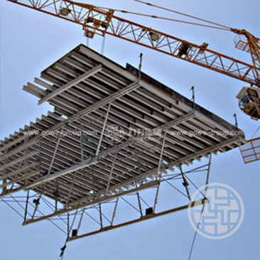
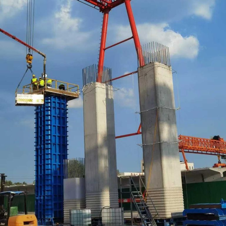
Stripping is not simply the reverse of erection. Concrete strength, curing, span, load history, and the next stage affect when support can be reduced. Reshoring may control loads on a young slab or lower floor. A Table Formwork arrangement can support repetitive floor-cycle planning, but removal and repositioning still require project-specific approval.
GOWE works across formwork and scaffolding systems, and we integrate research and development, production, sales, leasing, construction, and operation.
FAQ
Q: What Is a Shoring Scaffold Used for in Concrete Construction?
A: A shoring scaffold temporarily supports formwork and transfers loads from slabs, beams, or other concrete work to an approved surface. It is designed around a load path and stability arrangement, not only around access.
Q: How Is a Shoring Scaffold Different From a Supported Scaffold?
A: A shoring scaffold is arranged to carry temporary structural or formwork reactions. A supported scaffold is generally arranged for worker access, materials, or façade work. The same components may appear in both systems, but the load case, layout, bracing, access provisions, and approval requirements differ.
Q: How Is Shoring Scaffold Spacing Determined for Slab Formwork?
A: Spacing is determined from the formwork beam layout, slab and beam reactions, support capacity, height, bracing, receiving surface, and design information. It should not be selected from a generic spacing table without checking the complete arrangement.
Q: Can a Shoring Scaffold Also Be Used as a Working Platform?
A: Not automatically. A working platform needs its own access, decking, edge protection, loading, and fall-protection review. Use it for access only when the combined arrangement has been specifically designed and approved.
Q: When Can a Shoring Scaffold Be Removed After Concrete Pouring?
A: Removal depends on the approved stripping and reshoring sequence, concrete strength and curing, spans, loads, and the condition of the supported and lower floors. The responsible engineer or competent person must authorize the change; the pour date alone is not enough.