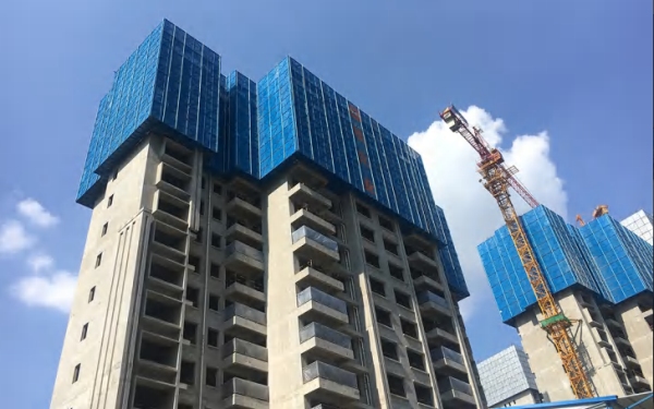
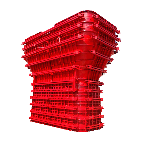
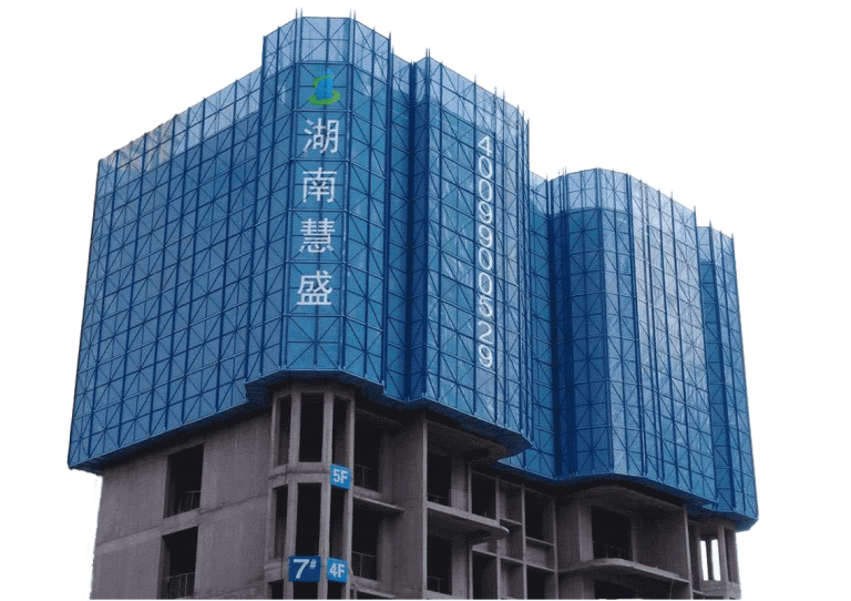
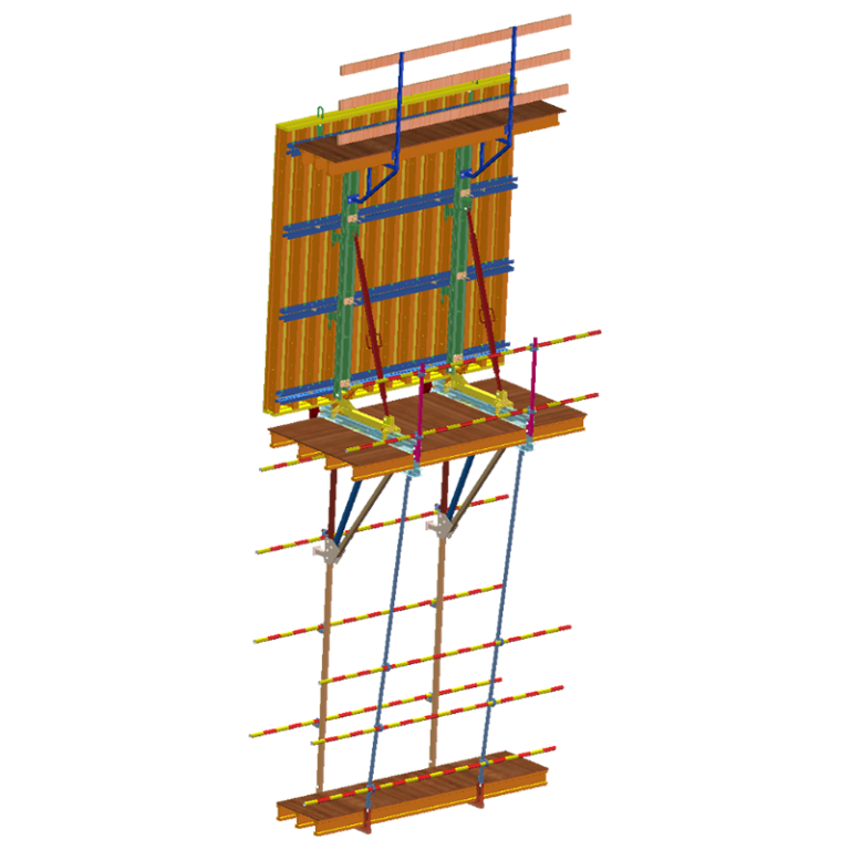

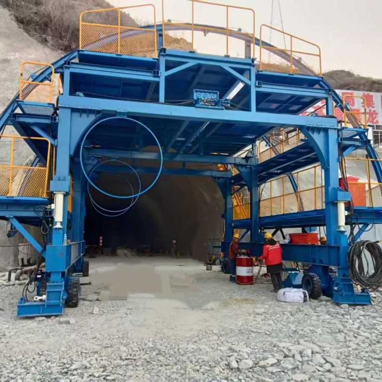
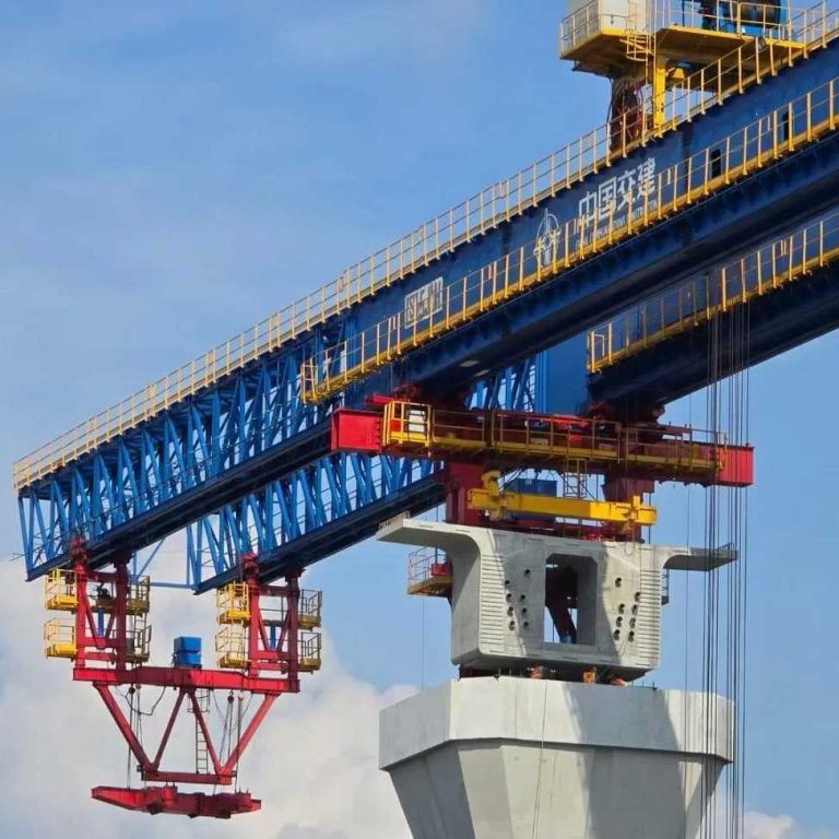
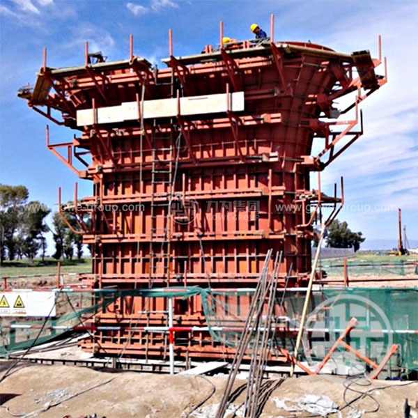

Concrete work becomes harder to control when the form face, frame, shoring, access route, reinforcement and permanent works are designed as separate packages. Treat a formwork frame as one responsibility within an integrated temporary works system.
What Should Contractors Define Before Integrating Formwork Frames?
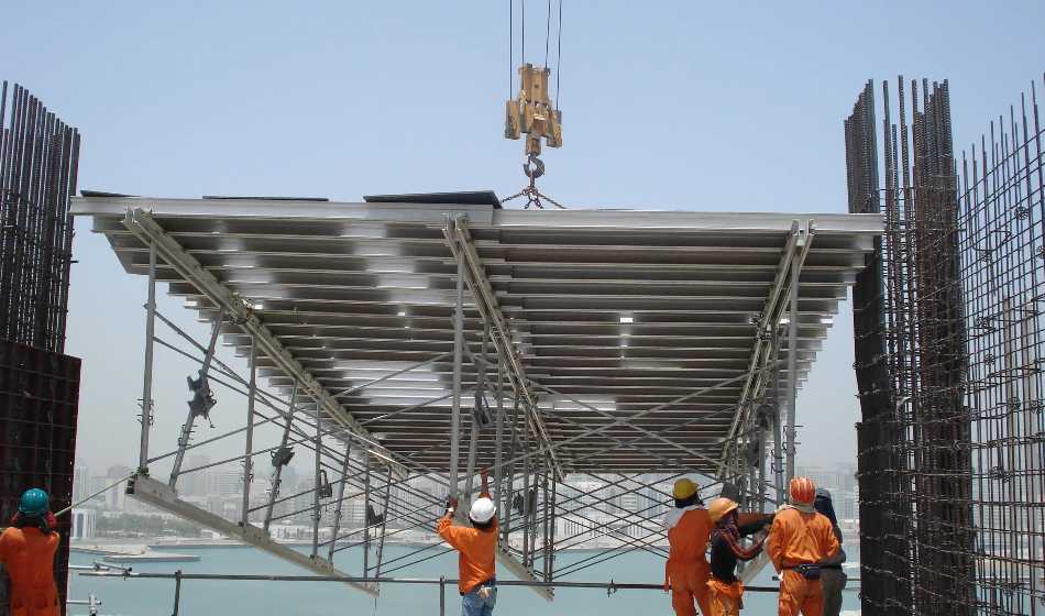
Where Do Formwork Frames End and the Support System Begin?
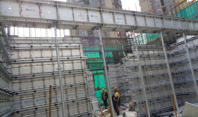
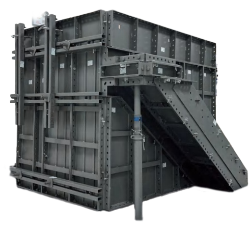
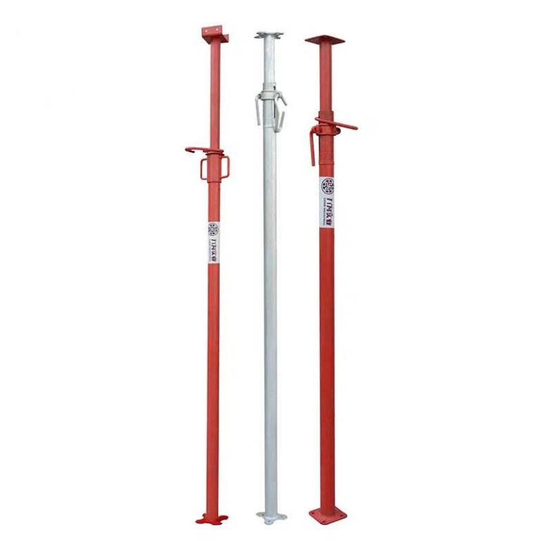
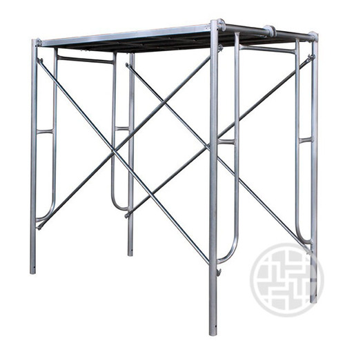
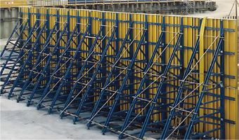
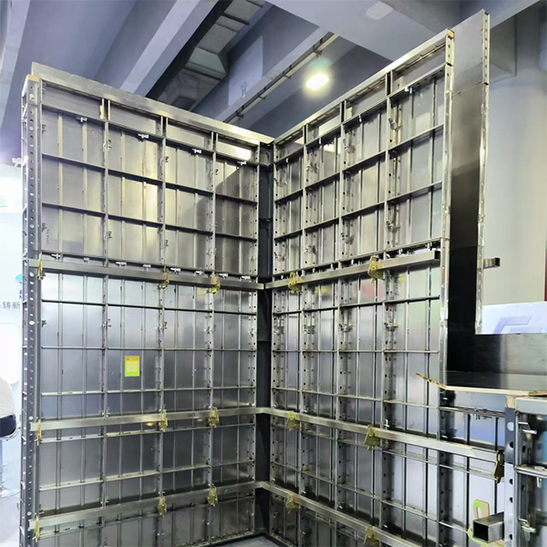
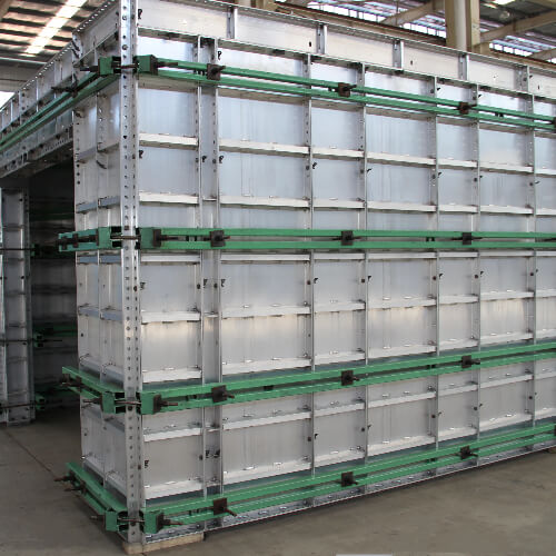
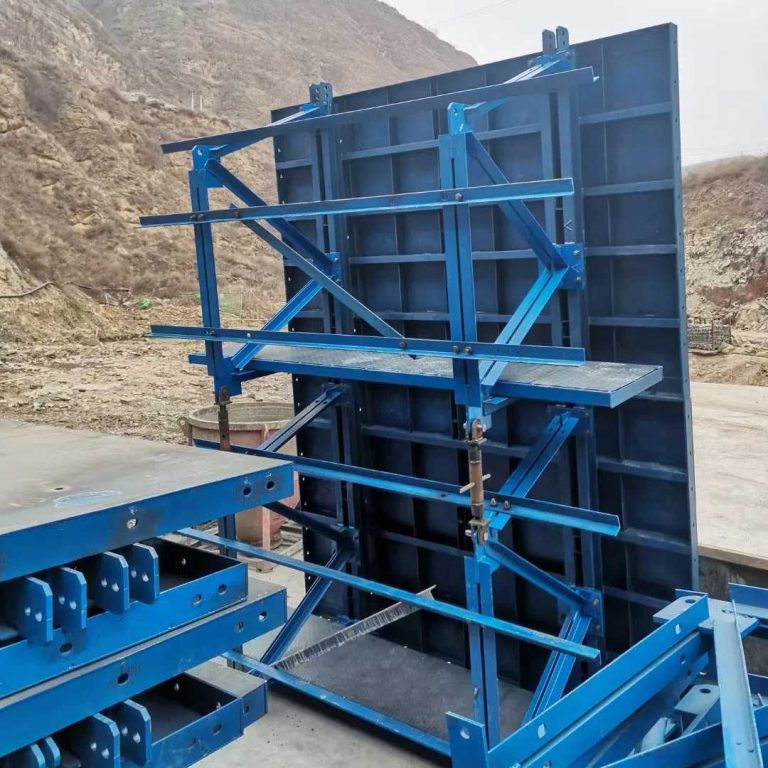
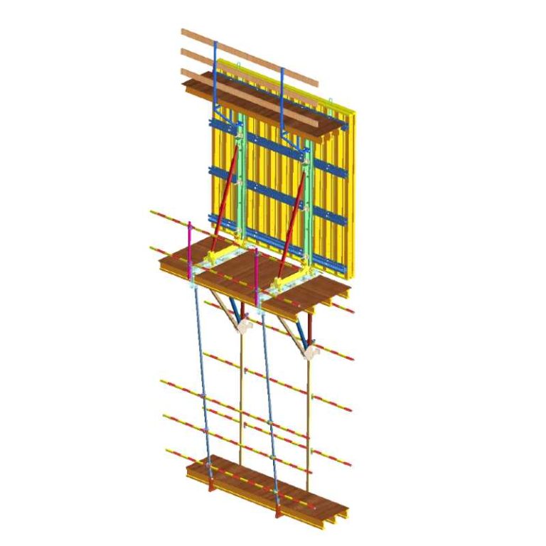
Begin with a clear component responsibility schedule. The form face or panel defines the concrete geometry and surface finish. Beams distribute concrete pressure to the supporting frame or table structure. The frame keeps the panels aligned and transfers loads to the supporting elements. Shoring—including props, towers, heads, bases and bracing—then carries those loads to the slab, ground or another approved existing structure.
This terminology matters. A complete temporary works system should not be described simply as formwork frames because frames are only one part of the assembly. Project documents should define the form face, framing, support, access and connection scopes separately. The final configuration, load capacity, working height and component compatibility must follow the applicable manufacturer instructions and project approvals.
Which Interfaces Belong to Formwork, Shoring, Access and Permanent Works?
An interface matrix can separate responsibilities into four areas: concrete forming, structural support, worker access and permanent works. Formwork controls dimensions, alignment, finish and stripping. Shoring controls stability, adjustment range, base reactions and load transfer to the supporting structure. Access systems control platforms, ladders, guardrails, routes and fall protection. Permanent works include reinforcement, embeds, sleeves, anchors, openings and the receiving slab or wall.
These functions should not be treated as interchangeable. An access platform is not automatically suitable simply because it is connected to a load-bearing support. Likewise, a permanent embed should not be used as a temporary tie unless the arrangement has been specifically designed and approved.
Why Should Table Formwork Be Treated as a Complete Formwork Unit?
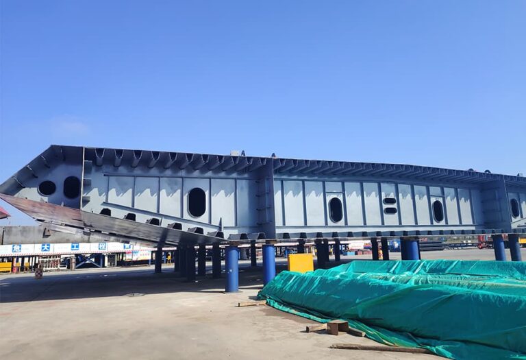
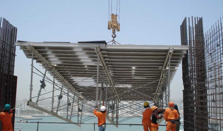
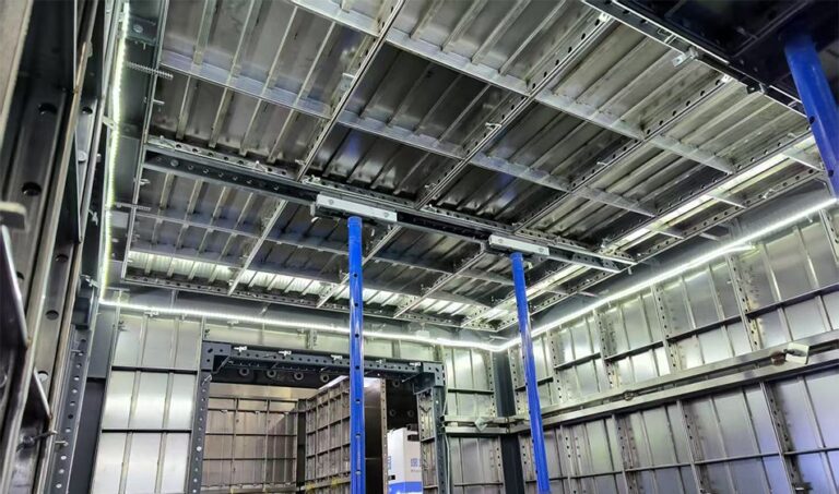
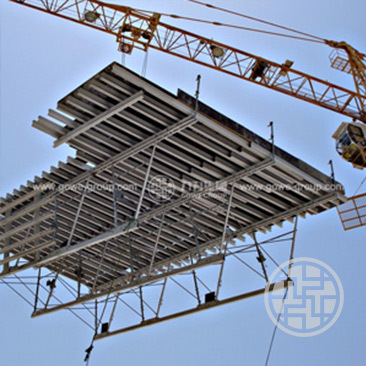
Table formwork is a coordinated temporary-works assembly consisting of an upper formwork structure—such as the form face, panels, primary beams and secondary beams—and a supporting shoring substructure, which may include steel legs or props, heads, braces and connection hardware. These elements are designed, moved and stripped as one coordinated unit. Referring to the entire assembly simply as a formwork frame can blur the distinction between the panel framing and the shoring substructure and may obscure critical checks such as leg spacing, head seating, lifting points, bracing and the bearing capacity of the supporting slab or ground.
The frame is one component of the table, while the table itself is the engineered formwork unit. Before it enters the pour zone, teams should confirm the geometry, centre of gravity, lifting method, support arrangement and stability of the complete assembly.
How Should Formwork Frames Connect With Shoring and Slab Support Systems?
Establish a Continuous Load Path From the Form Face to the Supporting Structure
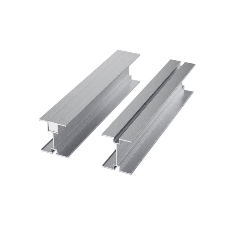
Ensure a continuous load path by tracing forces from the wet concrete through the form face, panels, secondary beams, primary beams, the formwork frame or table chassis, head jacks, props or shoring towers, and base plates, and ultimately into the load-bearing slab, foundation or ground. Include horizontal effects where the design requires them.
A continuous path also identifies where settlement or slip can occur. Check bearing, eccentricity, lateral restraint and the loading sequence. Capacity of an isolated prop does not prove the complete system if the head, brace, base or supporting slab fails first.
Check Heads, Beams, Bracing, Bases and Adjustment Ranges
Check interface dimensions and adjustment ranges at both ends of each support. Heads must seat the beam without point loading or unintended rotation. Beams need restraint against rolling. Bracing must remain effective at the selected height and must not clash with reinforcement or access routes. Bases must bear on an approved surface.
Record the actual extension of adjustable shoring and show the approved range and locking details.
Verify Compatibility Before Combining Components From Different Systems
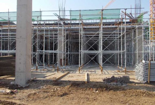
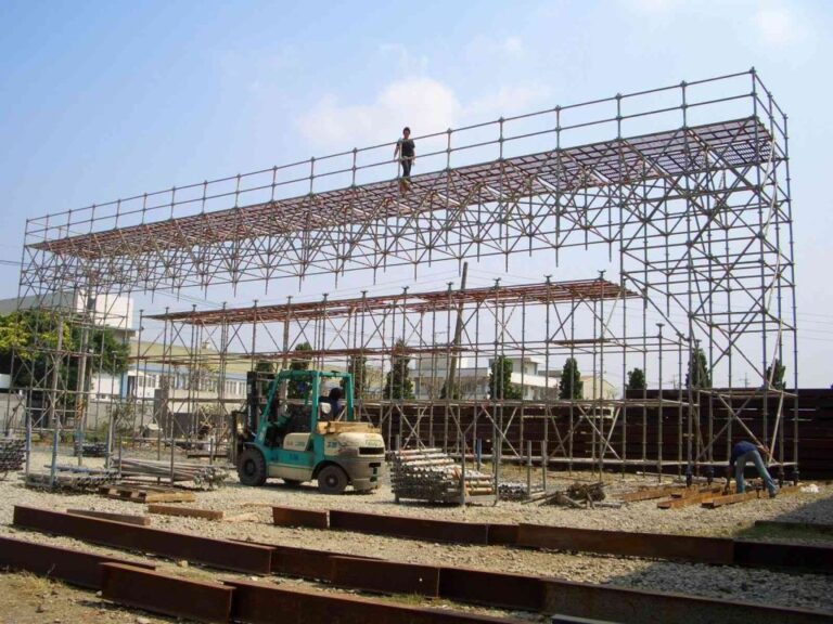
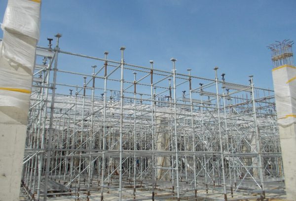
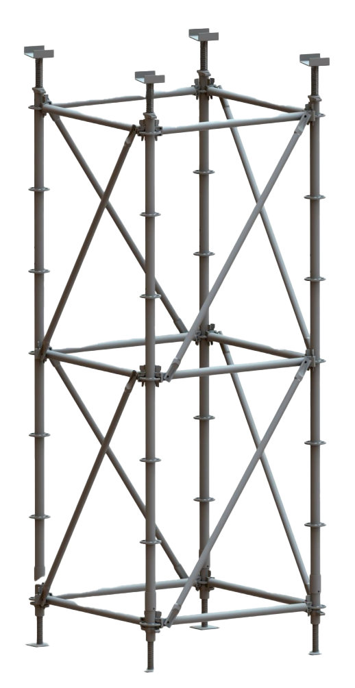
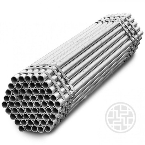
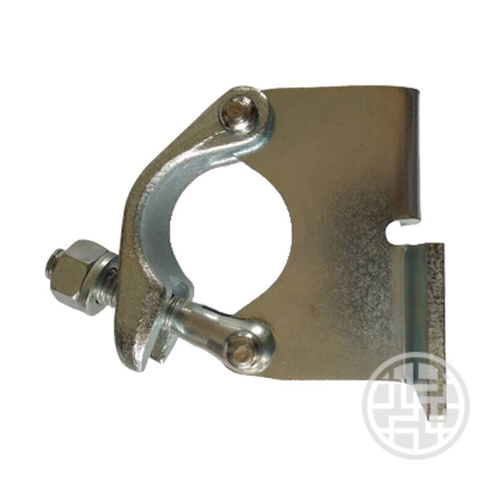
Do not combine components because pins, tubes or screw threads appear similar. A support assembly is a coordinated set of standards, ledgers, diagonal braces, base jacks, base collars and head jacks, not a collection of visually similar pieces. Wedge-pin connections are part of the system connection logic. The resulting assembly transmits vertical load and horizontal force through connected parts. Verify the approved configuration, component condition, connection details, selected adjustment range, design loads and required bracing before use. Do not intermix loose Ringlock components, such as ledgers, standards or diagonal braces, into custom table-formwork or slab-support assemblies unless the combined configuration has been structurally engineered, its load path and connections have been verified, and the arrangement has been approved in accordance with the relevant manufacturer requirements and project procedures.
The approved system logic is therefore part of the evidence: standards, ledgers and diagonal braces are not interchangeable with a formwork frame; base jacks, base collars and head jacks are not generic substitutes for table-formwork legs or heads. A project may use related equipment at an interface only after the complete load path, connection, bracing and adjustment range have been checked and the manufacturer and engineer have approved the arrangement.
While GOWE provides integrated formwork and scaffolding solutions across research and development, manufacturing, sales, leasing and project support, this broad system capability should not be interpreted as automatic approval for any site-specific combination of components. For each application, the project engineer must independently verify component capacities, connection details, load paths, bracing requirements and compatibility of the complete temporary-works configuration. For related system context, review Steel Prop; the project engineer must still approve the complete configuration.
How Can Formwork Frames Work With Scaffolding and Access Systems?
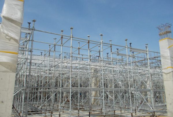
Separate Structural Support From Worker Access and Fall Protection
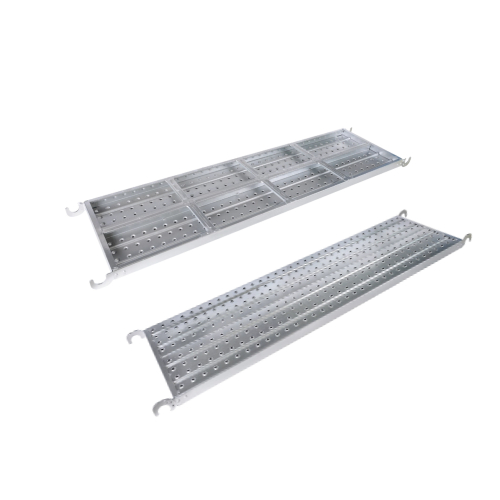
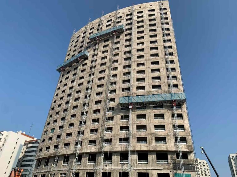
A shoring tower may carry concrete reactions without providing a compliant work platform. Provide an independent access solution or a specifically designed integrated platform with guarded edges, safe ladder access, toe boards and a verified load class. Keep access loads, stored materials and worker movement out of the calculation unless explicitly included. Related context: Frame Scaffolding.
Coordinate Platforms, Ladders, Guardrails and Material Routes
Reserve clear routes for panel installation, reinforcement, MEP inspection, surveying and concrete placement. Place platforms where workers can reach ties and connectors without climbing frames or leaning over guardrails. Confirm ladder clearance, guardrail continuity and routes for hoses and materials.
Plan Lifting and Repositioning Without Removing Critical Bracing
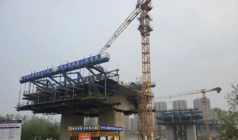
Show lifting points, crane radius, exclusion zones, landing locations and brace-removal order. Never remove a brace merely to make a load pass through. If a brace must change, provide temporary restraint, obtain approval and restore the configuration before workers enter. Check the next pour zone before moving the unit. Related lifting context: Hanging Basket Formwork.
How Do Formwork Frames Affect Rebar, MEP, Embeds and Openings?
Coordinate Reinforcement Congestion and Required Concrete Cover
Overlay frame legs, ties, walers, braces and anchor points with reinforcement zones. Check laps, couplers, beam and column congestion, and specified concrete cover. Resolve clashes in drawings, not by cutting a brace or bending a bar in the field without engineering approval.
Fix Sleeves, Anchors, Blockouts and Embedded Items Before the Pour
Locate MEP sleeves, anchor bolts, embedded plates, blockouts, pour stops and formwork openings on the coordinated set. Identify which item is fixed to permanent works and which is held by temporary formwork. Provide tolerances and a survey check before placement.
Use Coordinated Drawings and Change Control to Prevent Field Modifications
Use one revision-controlled drawing set. A late opening can alter a beam, tie, brace or support path. Review loads, access, stripping and re-shoring before accepting a field modification.
How Should Teams Manage the Integrated System Through the Concrete Cycle?
Review Coordinated Drawings, BIM Models and Trial Assemblies
Before fabrication or delivery, review geometry, interfaces, work space, lifting routes, sequence and temporary conditions. Trial-assemble unusual corners, transfer areas and congested embed zones. Close clashes before materials are released.
Complete a Multi-Trade Pre-Pour Handover
Formwork, reinforcement, MEP, surveying, concrete and safety representatives should inspect the same area. Confirm line and level, supports and braces, access, reinforcement and cover, embeds and openings, and pour sequence. Use one coordinated handover.
Monitor System Interfaces During Concrete Placement
Assign observers to watch frame movement, shoring settlement, joint leakage, platform interference and embed movement. Set stop-work triggers. If an interface changes, pause placement and obtain an approved correction.
Plan Stripping, Reshoring and Transfer to the Next Pour Zone
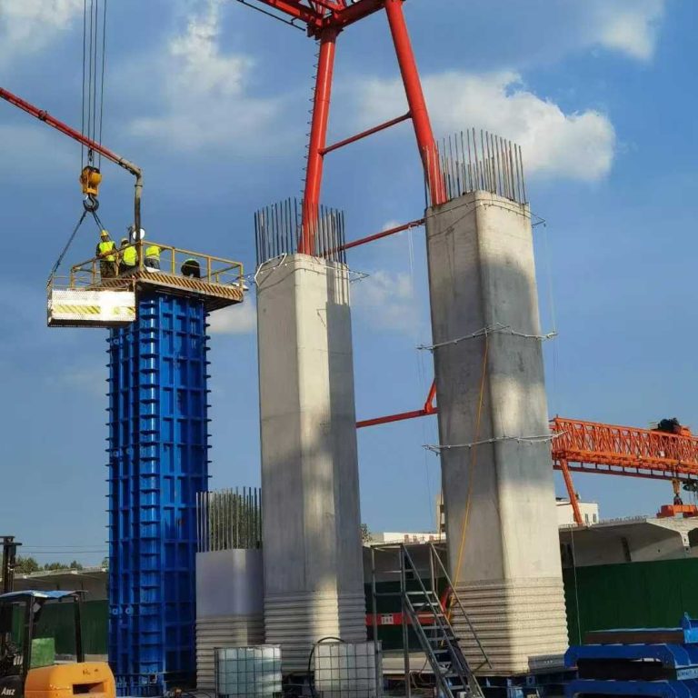
Stripping a formwork frame does not automatically release every support. Follow the engineered strength and reshoring sequence, protect green concrete and keep supports that still carry transfer loads. Plan the next zone before moving material.
FAQ
Q: Can Formwork Frames Be Used With Scaffolding and Shoring Systems?
Yes, when the complete configuration, load path, connections, bracing, access and supporting structure are reviewed and approved. Visual fit is not sufficient.
Q: How Do Formwork Frames Connect to Slab Support Systems?
Through engineered heads, beams, props or towers, bases and slab reactions. Check bearing, adjustment range, lateral restraint and slab capacity as one path.
Q: Can Components From Different Formwork Frames Be Combined Safely?
Only after dimensions, connection details, design loads, stiffness, condition and manufacturer approval are verified. Do not mix by appearance.
Q: How Should Formwork Frames Be Coordinated With MEP Openings and Embeds?
Show sleeves, anchors, plates and blockouts on the coordinated drawings, assign ownership, set tolerances and complete a multi-trade check before pouring.